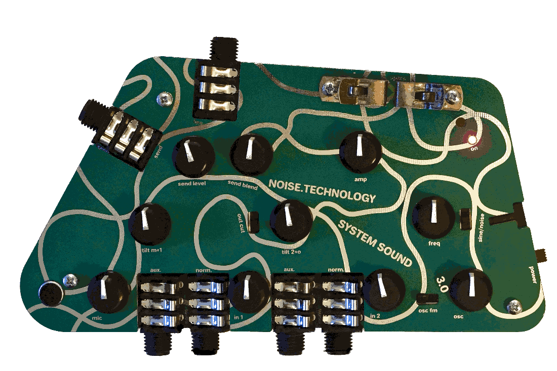
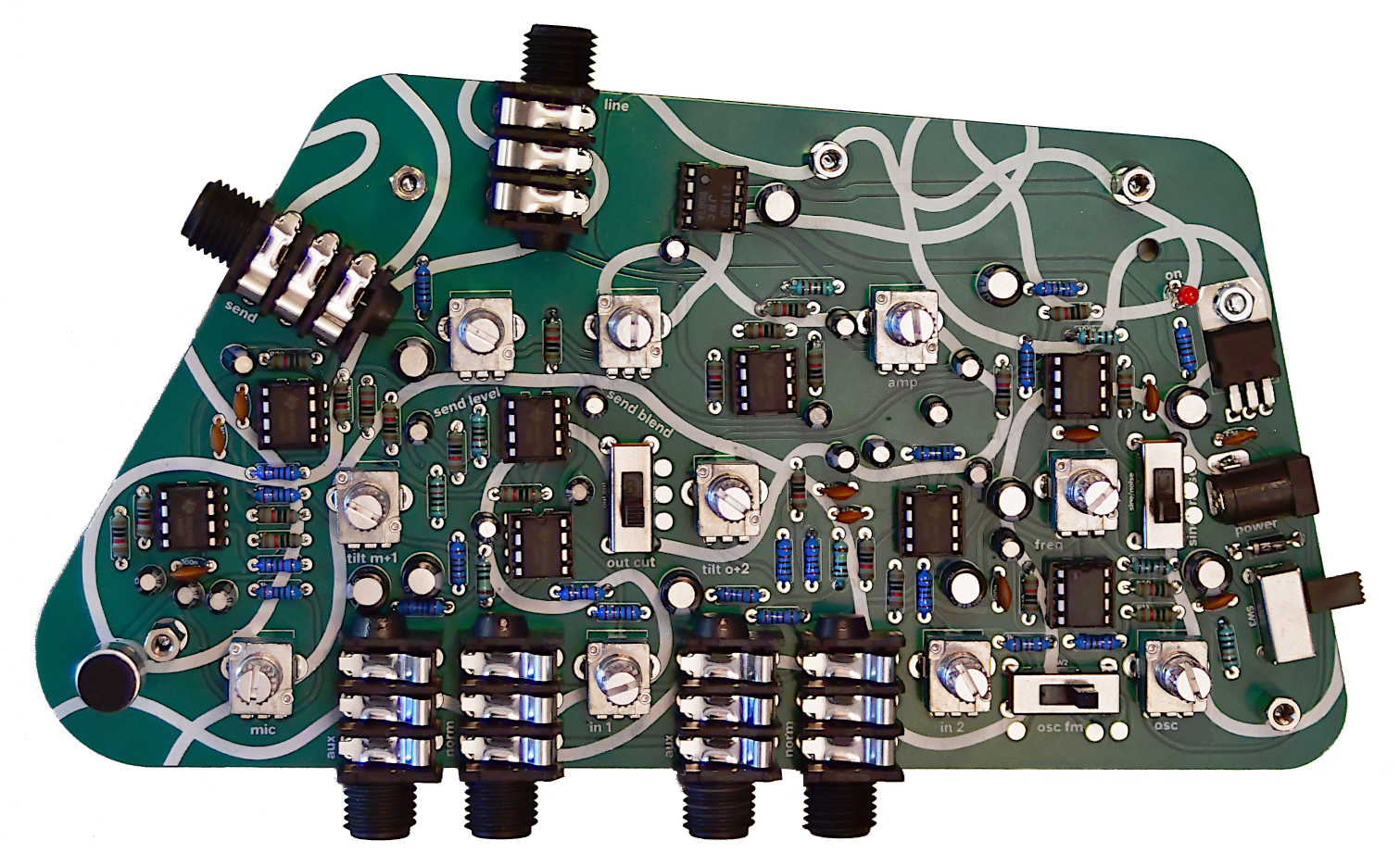
First, make sure you have all the parts and tools required. You can tick off the components in the included kit sheet or IBOM. The Schematic is available here, if you want it.
• Soldering iron or station, with cleaning sponge
• Solder
• Side cutters
• Philips #1 size (PH1) screwdriver
• Some masking tape may also come in handy
• As with all panel mounted components, it is important that the pots are soldered only after fastening to the lid/panel. Otherwise, the solder joints will be stressed as you tighten the nuts (this also applies to the 7805 regulator).
• It is also important that the switches are flush against the board, not just for aesthetic reasons. If a switch is skewed, it will be less mechanically stable, which may lead to breakages in the future. See photos below for more details.
• The two large mounting pins on the potentiometers should also be soldered, for mechanical stability. As all of the pots are the same value (Linear, 50Kohms), there’s no need to wait with soldering the mounting pins until after the circtuit works.
• Not all pins on the jacks perform an electrical function, but they should all be soldered (some may not be soldered in the photos – ignore this). All jacks should also be flush against the board, for mechanical reasons.
• As mentioned in the kit sheet, there is a preffered order in which you assemble the System Sound. Other orders are possible, but may be a bit more difficult. Follow the order in the kit sheet, or below. Take not the the mechanical instructions regardless – regarding pots, LED, microphone, etc. The order in the IBOM mostly corresponds to the one in the kit sheet, but not entirely (due to how the IBOM works).
Do the resistors first. I like to do them starting with the ones there are fewest of, and finishing with the most common ones (10K in this case). Placing all resistors before soldering will minimise errors and is quicker, but beginners may want to do one or two at a time.
One quick and neat way to do the resistors is to place the board in a box or PCB holder so the resistor leads can hang freely, and solder the resistors from the top. This saves time flipping the board over to bend the legs. It also makes soldering easier as you don’t have to navigate a forest of legs (or cut them off as you go). I call this technique ”Stockholm style” as people at workshops I’ve done at EMS and Fylkingen tend to do this.
You can build your System Sound without sockets if you like. It is more reliable, but means placing an IC in the wrong place or wrong-side-up will be much more troublesome. Recommended for experienced builders.
In either case, this is the time to mount the sockets or DIP chips. If you’re mounting the chips – take note of the orientation, and make sure you put the right chip in the right place. The chips have a U-shaped notch and/or a dot indicating up/pin1. The notches should all face up. The chips have markings: the oscillator is called PIC12F1840 (and you may want to socket it in case I release chips with new code). It’s in the bottom right of the board. The amp is called NJM113 but the labelling says JRC2113. It’s the topmost DIP chip. All the other chips are LM358s.
If you use the sockets, you can put the chips in now. Note the orientation etc. mentioned above.
As mentioned above, make sure the power switch is flush against the PCB. The best way is to solder one pin from above, check it is flat, and then do the rest.
The black protection diode can be done like the resistors. Make sure the white line aligngs with the one on the PCB.
As with the potentiometers, the 7805 regulator must be fastened mechanically before soldering. Push the legs through the mounting holes and then use the screw as a guide to position the regulator.
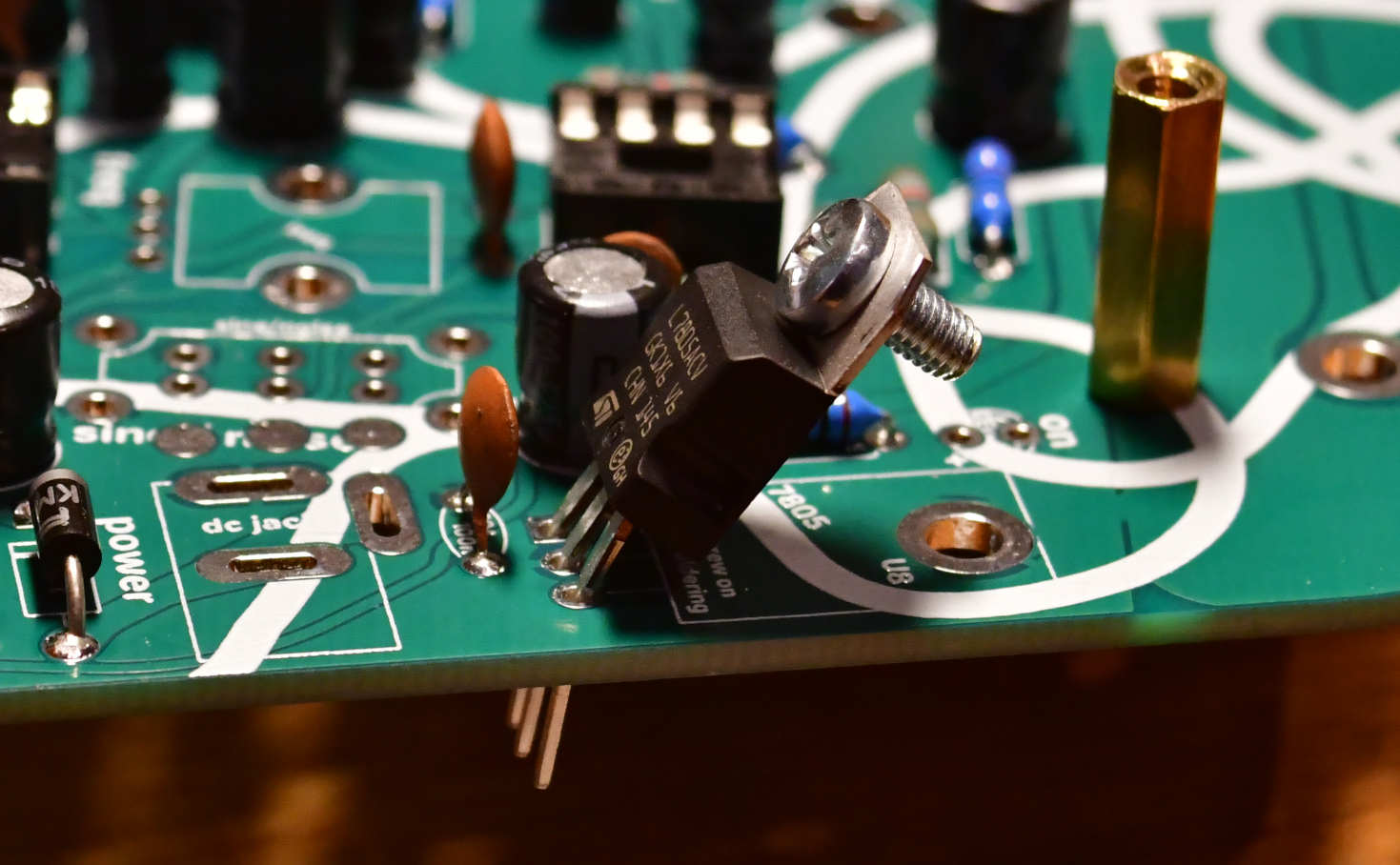
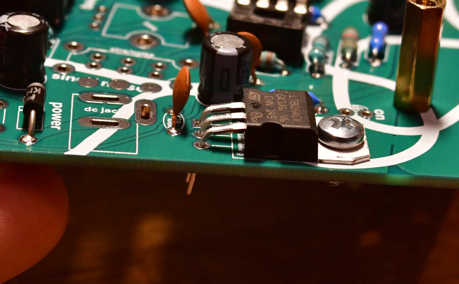
When it is in the right place, take out the screw and push it in from the bottom. Add a lock washer and nut and tighen.
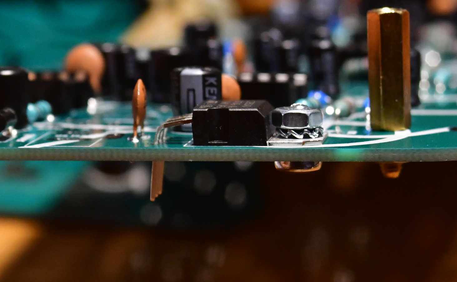
Solder after screwing in place. Cut off leads as usual, or ideally before soldering if you are the NASA type.
The capacitors should be straighforward. Note that the electrolytics, i.e. the black ones, are polarised. + = the long leg. Both + and - are indicated on the board, but some are a bit hard to see. Refer to the IBOM, you can zoom in closely.
The ceramic capacitors are all for filtering, 100nF for power filtering (boring), the others are in the EQ and DAC. Both can be modded if you’re into that. NOTE that C12 (100nF) has been flipped in my computer, so its silkscreen is on the back of the board. This is a mistake, you should put the capacitor on the front, with the others.
Put the audio jacks in place and solder them. They’re all the same and can only go in one way. As long as they’re flush against the board all should be well.
Then, place the DC power connector and bend the leads, but don’t solder it in place yet. Wait until the lid is in place. See below.
Now, a break from soldering. You can turn the iron off. It’s time to mount the standoffs and rubber feet.
The feed and standoffs are to be mounted in this order, from the bottom up: 6mm M3 screw, rubber foot, main PCB, 10mm M3 standoff, lid PCB, lock washer, 6mm M3 screw.
For the two speaker connectors, things are a bit different: the right one is like the other mounting standoffs, except that you insert a Fahnclip between lock washer and the screw.
The left one doesn’t have a rubber foot, so it needs an extra lock washer. That lock washer goes where the rubber foot goes otherwise.
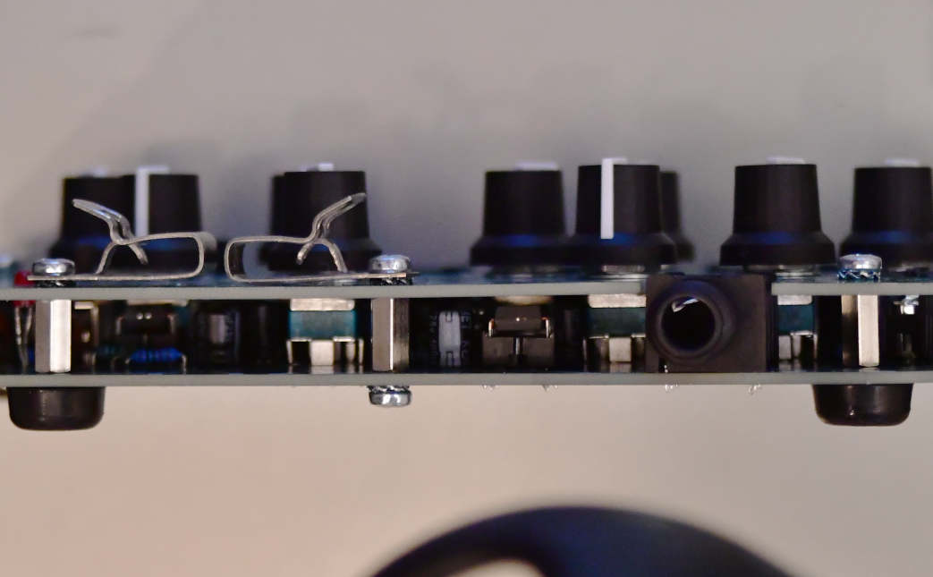
Two notes about the mechanical parts:
• Due to the lack of room around the microphone (in the lower left corner of the device) you may want to wait with that rubber foot until later. Especially if your soldering is a bit shaky – otherwise you might burn the foot, which is likely to smell terrible.
• use a PH1 screwdriver. Using the wrong screwdriver is in general not a good idea: you’ll strip the screws or not get things tight.
You can see a schematic representation of how to mount everything in the scematic. Or, you can look at images like this:
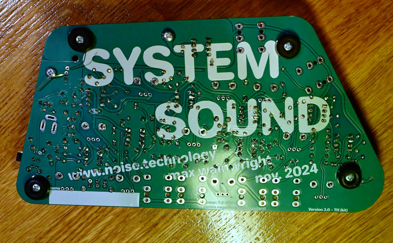
As with the power switch, the three control switches need to be flush against the board. The easiest way to assure this is to put them in place (orientation doesn’t matter) and solder one leg from the top. Gravity should do the rest, but make sure the switches are completely flat against the board, even without applying any pressure. When they are, do the pin diagonally across the one you did first, double check, and then do the rest of the pins.
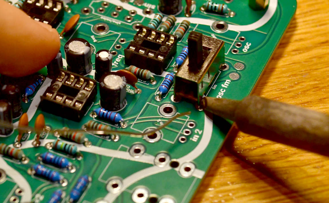
The LED is polarised. Long leg = +. Put the LED in place and bend the leads so it doesn’t fall out, but don’t solder it yet. First, do the electret steps below. Then, push the LED through the lid and solder it.
Put the potentiometers in place. They all have the same value and taper. Don’t solder them yet.
The electret microphone is the trickiest bit on System Sound, but really not so difficult. It doesn’t matter if it ends up a bit wonky as long as it pokes through the lid.
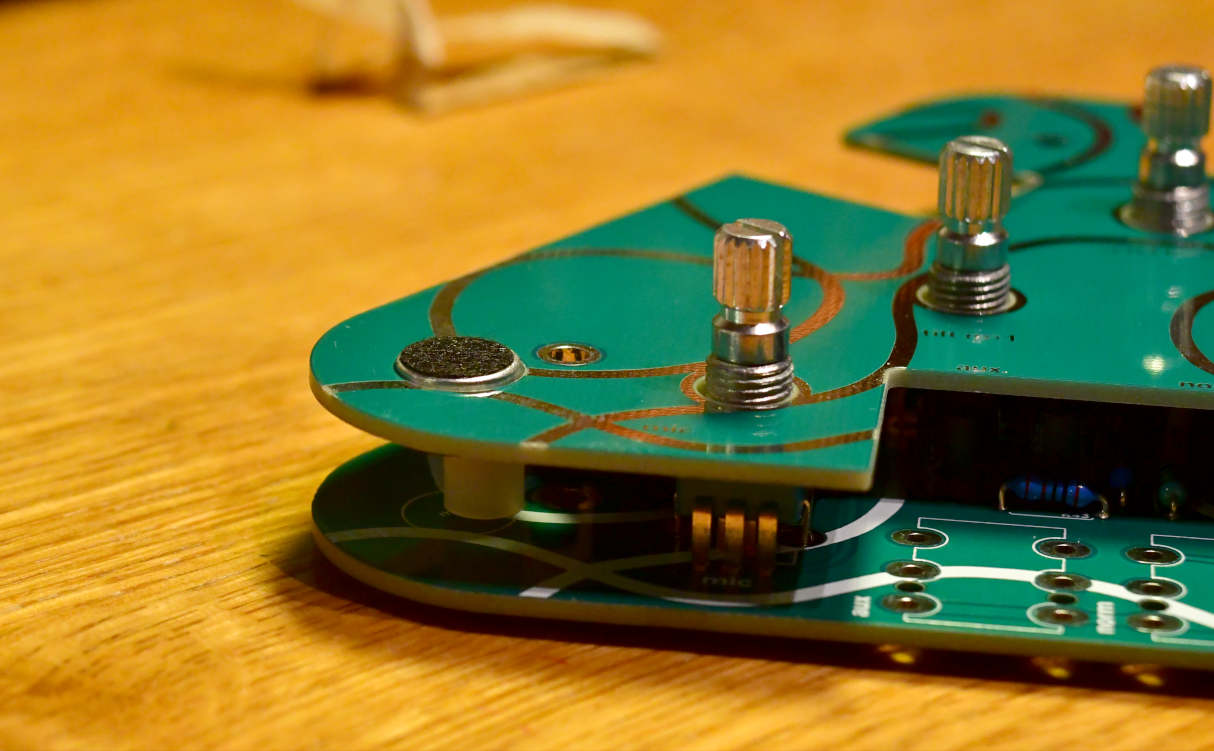
The mic is mounted on top of a plastic unthreaded spacer. Push the microphone leads through the spacer, and then the board. Bend the leads so it doesn’t fall out The microphone is polarised, but if you do it wrong you will notice in the next step.
Now, mount the lid and screw it on. The microphone should poke through the lid as in the image above.
solder one lead on the microphone. Then, use the screwdriver to poke the washer until it is under the microphone body, and not ”outside” it. Push down on the mic so it stays in place and reheat the lead you did. If things stay the same, now to the other lead.
Push down. Note that the spacer fits under the mic:
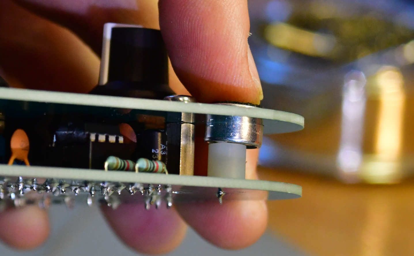
Then reheat the solder joint.
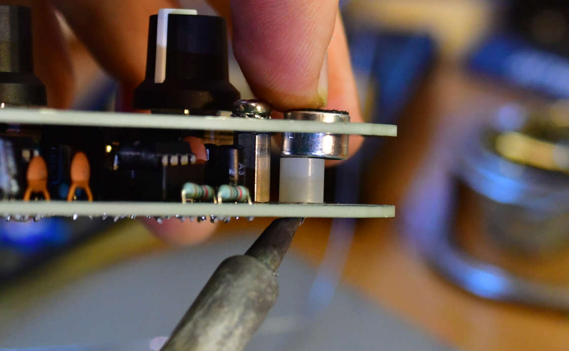
You can now push the LED through the panel and solder it.
Then, screw on the washers and nuts for the pots, and then solder them.
Now, push the DC connector in sideways, as if inserting a plug.
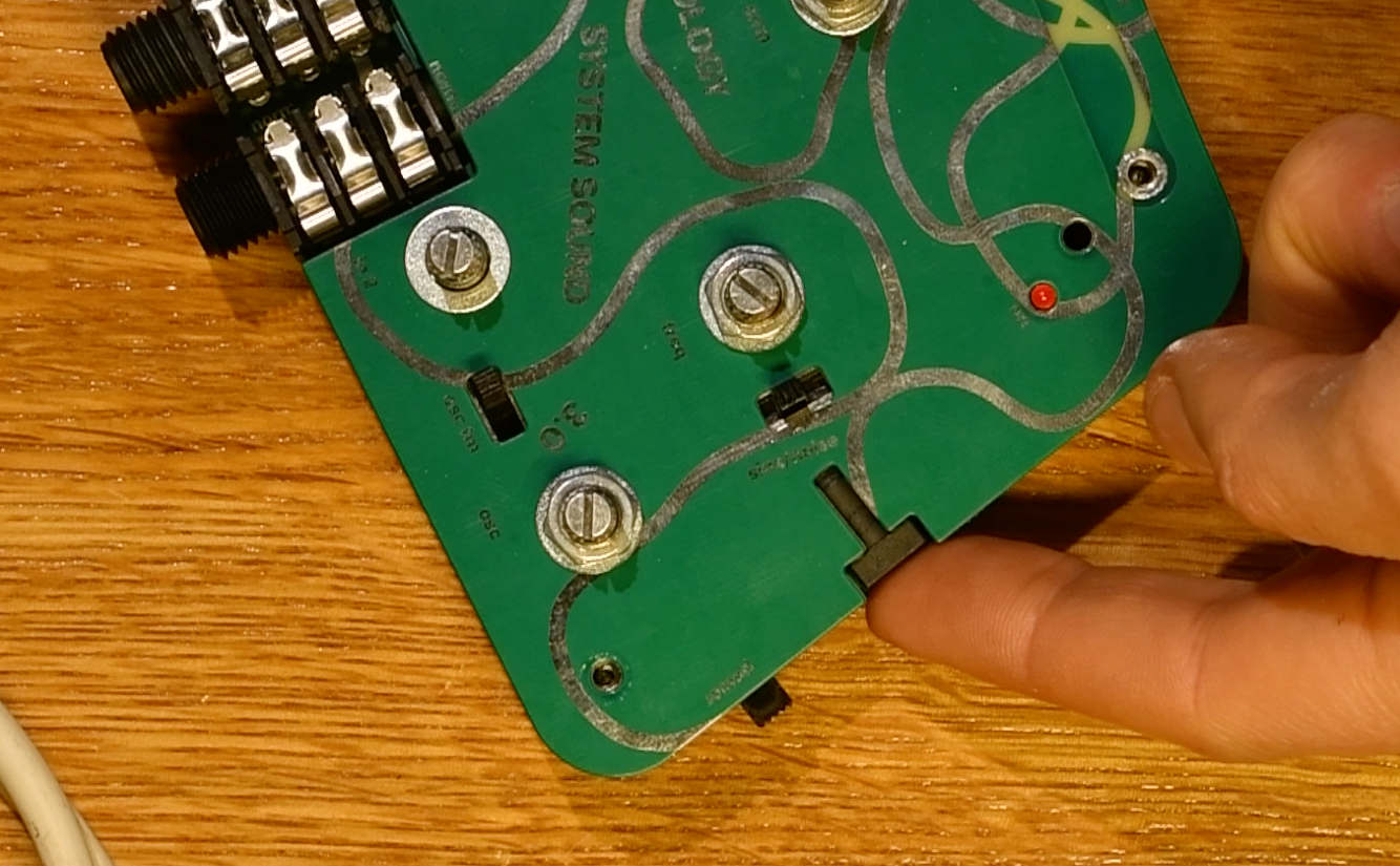
Solder it in place when it fits snugly in place. You can use the same technique as for the electret mic (see above), doing one pad first and then reheating whilst pushing. Pushing the jack in ensures all the force of inserting jacks goes into the standoffs and pots (via the lid), instead of into the solder joints. That would be bad.
Done! Test the device, and if all is well, put on the knobs. Enjoy!
